

Updated:
Originally Published:
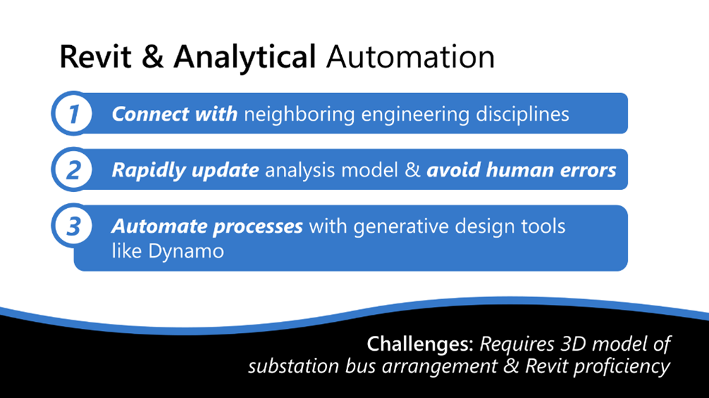
Integrations between BIM (Building Information Modeling) and structural analysis tools are reshaping the possibilities for modeling in substation engineering. Once integrated, engineering teams can create coordinated 3D models that have the power to connect across disciplines while also allowing users to extract element data.
The traditional approach to rigid bus analysis via FEA (Finite Element Analysis) models can be a tedious and time-consuming process, with technicians and engineers often duplicating efforts. But with integrations between BIM (Building Information Modeling) and structural analysis tools, that’s changing.
Today, engineering teams can automate rigid bus analytical model generation in just a few clicks—transforming how substations are designed, analyzed, and delivered and opening up possibilities for time-saving engineering and drafting automations.
In a conventional workflow, bus arrangement modeling and structural analysis happen in silos. A structural engineer references the 3D model or 2D drawing to build an analysis model manually in an FEA software.
This traditional approach creates:
A modern workflow eliminates this disconnect by integrating BIM and FEA platforms. This allows engineers to create analytical models directly from 3D Revit models—reducing rework, improving consistency, and accelerating delivery.
The process begins in Revit, where rigid bus components—such as insulators, fittings, and structural members—are modeled using structural families.
Revit’s built-in “Analytical Automation” tool, powered by a Dynamo script, enables users to generate analytical models using only the Revit model.
This built-in script uses your modeled components to create analytical elements that FEA tools can understand, including analytical members, nodes, and boundary conditions.
Once the analytical model is ready, you can export it into tools like:
These plug-ins preserve analytical data, including:
This seamless handoff eliminates the need to rebuild the model in your FEA tool—saving time and maintaining consistency with your design intent.
Autodesk Robot offers the smoothest integration, with full two-way data sharing and native Revit support.
RISA and SAP2000 require plug-ins. While still highly effective, users may run into minor compatibility issues depending on software versions, modeling practices, or unsupported family types.
The key takeaway? The more consistent and clean your modeling practices are in Revit, the more accurate and efficient your analysis will be—regardless of the platform you are using.
Automation is only as good as the inputs. Here are essential tips to ensure the process works as intended:
Revit’s out-of-the-box Analytical automation tool depends on the use of structural family types. Avoid using architectural or generic components for anything that you want to create analytical elements from unless you want to customize the Dynamo script.
Be consistent in how you model elements. For example:
This ensures correct I/J end assignments in FEA tools.
Avoid fractional misalignments or skewed geometry. Snap to grid lines, use reference planes, and align components clearly to ensure the analytical model reflects actual geometry.
Revit’s material settings influence analytical properties. Switching from steel to aluminum, for example, automatically updates the analytical model’s output—no rework needed.
The benefits don’t stop at analysis. This integrated approach opens the door to full vertical coordination between engineering and detailing.
The result: a connected design ecosystem where engineers, designers, and detailers work from a single, consistent source of truth.
Even on smaller projects, this workflow saves time. But on larger, more complex substations, the results are substantial:

In addition to saving hours (or days), you’ll reduce costly rework, eliminate duplicated modeling effort, and improve overall coordination between design and analysis to ensure coordinated project delivery.
While powerful, this workflow isn’t plug-and-play without some forethought:
For most teams, though, the advantages of automation and integration far outweigh the potential drawbacks. With proper planning and disciplined modeling, this new workflow can transform how substation engineering is done.
Rigid bus analytical model creation does not have to be time-consuming. By automating model creation and integrating Revit with trusted FEA tools, structural engineers can drastically improve efficiency, accuracy, and collaboration. This workflow bridges the gap between BIM coordination and structural analysis while helping engineering teams deliver better results, faster. As adoption grows, automated rigid bus analysis is poised to become the new standard in the industry.
Beta Engineering is a substation EPC company headquartered in Pineville, Louisiana, with an office in San Diego. Since 1975, we’ve partnered with utilities across the U.S. to deliver high-voltage substation and transmission projects with lasting reliability. Contact our team to learn how we apply over 50 years of industry experience to help our clients design and build with greater confidence and less rework.
Updated:
September 30, 2025
Updated:
Originally Published:
Integrations between BIM (Building Information Modeling) and structural analysis tools are reshaping the possibilities for modeling in substation engineering. Once integrated, engineering teams can create coordinated 3D models that have the power to connect across disciplines while also allowing users to extract element data.
The traditional approach to rigid bus analysis via FEA (Finite Element Analysis) models can be a tedious and time-consuming process, with technicians and engineers often duplicating efforts. But with integrations between BIM (Building Information Modeling) and structural analysis tools, that’s changing.
Today, engineering teams can automate rigid bus analytical model generation in just a few clicks—transforming how substations are designed, analyzed, and delivered and opening up possibilities for time-saving engineering and drafting automations.
In a conventional workflow, bus arrangement modeling and structural analysis happen in silos. A structural engineer references the 3D model or 2D drawing to build an analysis model manually in an FEA software.
This traditional approach creates:
A modern workflow eliminates this disconnect by integrating BIM and FEA platforms. This allows engineers to create analytical models directly from 3D Revit models—reducing rework, improving consistency, and accelerating delivery.
The process begins in Revit, where rigid bus components—such as insulators, fittings, and structural members—are modeled using structural families.
Revit’s built-in “Analytical Automation” tool, powered by a Dynamo script, enables users to generate analytical models using only the Revit model.
This built-in script uses your modeled components to create analytical elements that FEA tools can understand, including analytical members, nodes, and boundary conditions.
Once the analytical model is ready, you can export it into tools like:
These plug-ins preserve analytical data, including:
This seamless handoff eliminates the need to rebuild the model in your FEA tool—saving time and maintaining consistency with your design intent.
Autodesk Robot offers the smoothest integration, with full two-way data sharing and native Revit support.
RISA and SAP2000 require plug-ins. While still highly effective, users may run into minor compatibility issues depending on software versions, modeling practices, or unsupported family types.
The key takeaway? The more consistent and clean your modeling practices are in Revit, the more accurate and efficient your analysis will be—regardless of the platform you are using.
Automation is only as good as the inputs. Here are essential tips to ensure the process works as intended:
Revit’s out-of-the-box Analytical automation tool depends on the use of structural family types. Avoid using architectural or generic components for anything that you want to create analytical elements from unless you want to customize the Dynamo script.
Be consistent in how you model elements. For example:
This ensures correct I/J end assignments in FEA tools.
Avoid fractional misalignments or skewed geometry. Snap to grid lines, use reference planes, and align components clearly to ensure the analytical model reflects actual geometry.
Revit’s material settings influence analytical properties. Switching from steel to aluminum, for example, automatically updates the analytical model’s output—no rework needed.
The benefits don’t stop at analysis. This integrated approach opens the door to full vertical coordination between engineering and detailing.
The result: a connected design ecosystem where engineers, designers, and detailers work from a single, consistent source of truth.
Even on smaller projects, this workflow saves time. But on larger, more complex substations, the results are substantial:
In addition to saving hours (or days), you’ll reduce costly rework, eliminate duplicated modeling effort, and improve overall coordination between design and analysis to ensure coordinated project delivery.
While powerful, this workflow isn’t plug-and-play without some forethought:
For most teams, though, the advantages of automation and integration far outweigh the potential drawbacks. With proper planning and disciplined modeling, this new workflow can transform how substation engineering is done.
Rigid bus analytical model creation does not have to be time-consuming. By automating model creation and integrating Revit with trusted FEA tools, structural engineers can drastically improve efficiency, accuracy, and collaboration. This workflow bridges the gap between BIM coordination and structural analysis while helping engineering teams deliver better results, faster. As adoption grows, automated rigid bus analysis is poised to become the new standard in the industry.
Beta Engineering is a substation EPC company headquartered in Pineville, Louisiana, with an office in San Diego. Since 1975, we’ve partnered with utilities across the U.S. to deliver high-voltage substation and transmission projects with lasting reliability. Contact our team to learn how we apply over 50 years of industry experience to help our clients design and build with greater confidence and less rework.
Related Services:


